はじめに
これまで RasPi から出力した PWM 信号でモーターを制御したり,音を鳴らしたり,PWM 関連の話が続いてますが,今回もまた PMW の話.モータードライバ MX1508 は外部電源を供給できるので問題にならなかったが,今後たくさんのモーターを一度に制御するには RasPi からの電力だけでは足りない.
今回は PCA9685 を使って色々制御してみる.
PCA9685 について
今回用意したモジュールはこれ.クローンがたくさん流通しているので適当に安い物のを選べばいい.

利用するアドレスは 0x40, 0x70 の 2 つ.0x70 は All Call アドレスで,モジュールを複数接続した場合に利用するらしい.
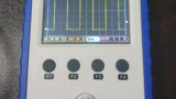
$ i2cdetect -y 1
     0  1  2  3  4  5  6  7  8  9  a  b  c  d  e  f
00:          -- -- -- -- -- -- -- -- -- -- -- -- --
10: -- -- -- -- -- -- -- -- -- -- -- -- -- -- -- --
20: -- -- -- -- -- -- -- -- -- -- -- -- -- -- -- --
30: -- -- -- -- -- -- -- -- -- -- -- -- -- -- -- --
40: 40 -- -- -- -- -- -- -- -- -- -- -- -- -- -- --
50: -- -- -- -- -- -- -- -- -- -- -- -- -- -- -- --
60: -- -- -- -- -- -- -- -- -- -- -- -- -- -- -- --
70: 70 -- -- -- -- -- -- --
この手の中国から送られてくるモジュールはピンヘッダがハンダ付けされた状態の物が多いが,かなりの確率でピンヘッダが曲がったままハンダ付けされていたり,輸送途中でピンヘッダが曲がったりしている.例によって今回も一部ピンヘッダが曲がった状態でハンダ付けされていたので,ちょっと手直しする.ピンヘッダをハンダ付けしてない状態で販売してほしい...
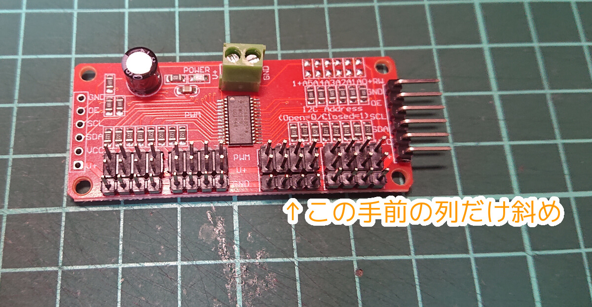
ピンヘッダの傾き修正,L 字ピンヘッダとスクリュー端子を通常のピンヘッダへ変更.
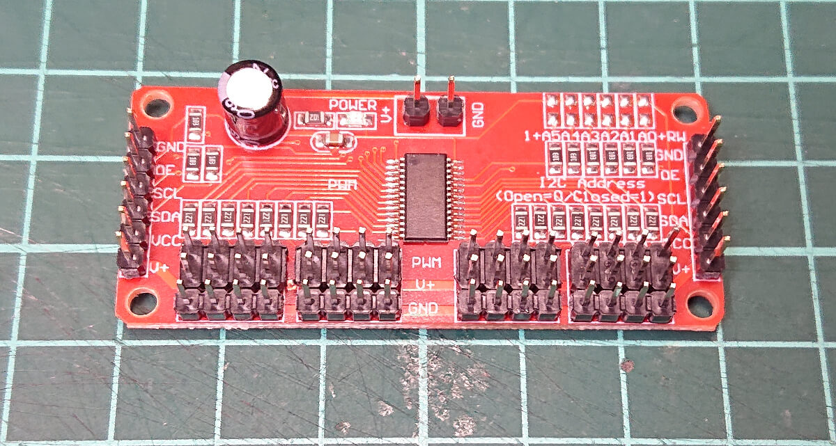
ピンヘッダの交換にあたっては,エンジニアのハンダ吸取器 SS-02 がおすすめ.先端が硬い一般的なハンダ吸い取り器と違って先端がシリコンチューブになっており,基板に密着させることで高確率できれいににハンダ吸い取りができる.

動作確認
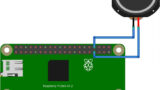
次のように配線する.PCA9685 の基板を描くのが面倒だったので Adafruit から拝借.
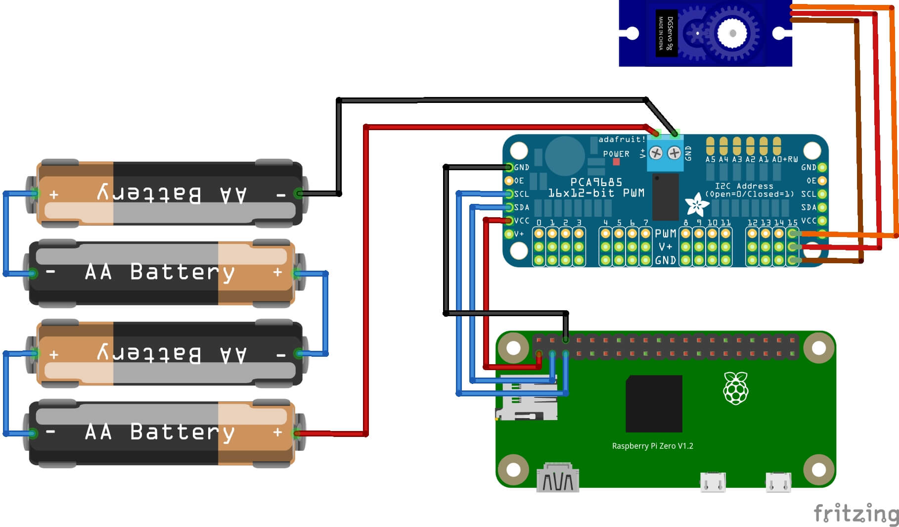
簡単に動作確認するため,ライブラリも Adafruit が用意しているものを使う.
ライブラリをインストールする.
$ pip3 install Adafruit_PCA9685プログラムを用意する.PWM を出力したい端子に合わせて set_pwm の第一引数を変更する.
# Simple demo of of the PCA9685 PWM servo/LED controller library.
# This will move channel 0 from min to max position repeatedly.
# Author: Tony DiCola
# License: Public Domain
from __future__ import division
import time

# Import the PCA9685 module.
import Adafruit_PCA9685


# Uncomment to enable debug output.
#import logging
#logging.basicConfig(level=logging.DEBUG)

# Initialise the PCA9685 using the default address (0x40).
pwm = Adafruit_PCA9685.PCA9685()

# Alternatively specify a different address and/or bus:
#pwm = Adafruit_PCA9685.PCA9685(address=0x41, busnum=2)

# Configure min and max servo pulse lengths
servo_min = 150  # Min pulse length out of 4096
servo_max = 600  # Max pulse length out of 4096

# Helper function to make setting a servo pulse width simpler.
def set_servo_pulse(channel, pulse):
    pulse_length = 1000000    # 1,000,000 us per second
    pulse_length //= 60       # 60 Hz
    print('{0}us per period'.format(pulse_length))
    pulse_length //= 4096     # 12 bits of resolution
    print('{0}us per bit'.format(pulse_length))
    pulse *= 1000
    pulse //= pulse_length
    pwm.set_pwm(channel, 0, pulse)

# Set frequency to 60hz, good for servos.
pwm.set_pwm_freq(60)

print('Moving servo on channel 0, press Ctrl-C to quit...')
while True:
    # Move servo on channel O between extremes.
    pwm.set_pwm( 9, 0, servo_min)
    pwm.set_pwm(11, 0, servo_min)
    pwm.set_pwm(13, 0, servo_min)
    pwm.set_pwm(15, 0, servo_min)
    time.sleep(1)
    pwm.set_pwm( 9, 0, servo_max)
    pwm.set_pwm(11, 0, servo_max)
    pwm.set_pwm(13, 0, servo_max)
    pwm.set_pwm(15, 0, servo_max)
time.sleep(1)おわりに
RaspberryPi で簡単に PCA9685 の動作確認をした.
ロボカムのハードウェア面は概ね部品が揃ったので,あとは適当な制御ソフトを作る.

コメント